Category
- Bar & Hollow Bar
- Strip,Coil,Wire
- Plate & Sheet
- Tube & Pipe
- Forged
- Titanium Products
- Commodity Ingot
- Precise Machining Parts
Contact us
- Tel:+86-13880247006
- E-mail: sales@steelgr.com
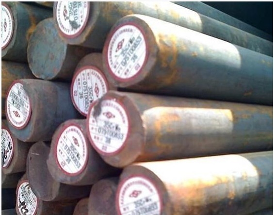
Our Products : Bar & Hollow Bar : 15GrMO Bar
| Standard: | AISI, ASTM, UNS, SAE, JIS, B.S., DIN |
| Grades: | |
| Dimensions(mm): | 1mm-2000mm |
| Place of Origin: | Sichuan, China (Mainland) |
| Technique: | Hot-rolled |
| Payment Terms: | 30% advanced payment,the balance will be paid before shipment. |
| Minimum Order Quantity: | 1.5 Ton/Tons |
| Port: | Chongqing & Shanghai |
| Packaging Details: | in bundle according to your requirement |
| Delivery Time: | about 30-90 days |
| Supply Ability: | 500000 Ton/Tons per Month |
Detailed Product Description
15GrMO Bar
Chemical composition:
| |
C
|
Mn
|
Si
|
Cr
|
Mo
|
Ni
|
Nb+Ta
|
S
|
P
|
|
15CrMo
|
0.12~0.18
|
0.40~0.70
|
0.17~0.37
|
0.80~1.10
|
0.40~0.55
|
≤0.30
|
_
|
≤0.035
|
≤0.035
|
The 15CrMo perform standard: GB / T 3077-2006
15CrMo weldability:
1 welding materials:
For the 15CrMo steel welding work characteristics, based on past experience with reference to the welding process card abroad, we selected two programs welding test.
The program Ⅰ: welding preheat ER80S-B2L wire, TIG welding primer E8018-B2 electrodes, SMAW cover up, local heat treatment after welding.
Program Ⅱ: ER80S-B2L wire, TIG welding primer, filling arc welding E309Mo-16 electrodes, welding rod cover up, no post-weld heat treatment. Wires and rods for chemical composition and mechanical properties are shown in Table 1.
3 welding test results:
The pilot programs tensile test Bending test impact toughness test aky (J/cm2)
Tensile strength δb / Mpa fracture site bending angle the surface bend back bend weld fusion line heat-affected zone (the HAZ)
Ⅰ 550/530, the base material 50. Pass Pass 84.8 162 135.6
Program Ⅱ 525/520 base material 50. Pass Pass 79.4 109.2 96.7
Welding process:
Program Ⅰ: welding preheat ER80S-B2L wire, T1G welding primer. E8018-B2 electrodes SMAW cover the surface, the local post-weld heat treatment.
Program Ⅱ: ER80S-B2L wire T1G welding primer. E309Mo-16 electrodes, welding rod cover up filled arc welding, post-weld heat treatment. Wires and rods for chemical composition and mechanical properties are shown in Table 1.
Table 1 welding materials of chemical composition and mechanical properties
Model C Mn Si Cr Ni Mo S P ΔB / MPa δ,%;
ER80S-B2L ≤ 0.05 0.70.41.2 <0.20.5 ≤ 0.025 ≤ 0.025 ≤ 500 25;
E8018-B2 0.070.7 0.3 1.1 0.5 ≤ 0.04 ≤ 0.03 550 19;
E309Mo-16 ≤ 0.12 0.5 ~ 2.5 0.9 22.0 ~ 25.0 12.0 ~ 14.0 2.0 ~ 3.0 ≤ 0.025 ≤ 0.035 550 25;
Welding preparation:
The specimen with the the 15CrMo steel pipe specifications φ325 × 25, groove type and dimensions shown in Figure 1.
With the angle grinder before welding inside and outside the groove and the groove edge 50mm within polished to expose the metallic luster, and then cleaned with acetone.
Specimen horizontal fixed position, and their counterparts in a gap of 4 mm, GTAW circumferentially uniform spot welding six solid at point length should be not less than 20mm. The electrode according to the specification of Table 2 for baking.
Electrode baking specification
The electrode model baking temperature holding time
E8018-B2 300 ℃ 2h
E309Mo-16 150 ℃ 1.5h
Process parameters:
Press the need for preheating before welding program Ⅰ preheat temperature formula, according to calculations made Tto-Bessyo:
To = 350 √ [C] -0.25 (° C) Where To - preheat temperature, ℃.
[C] = [C] x [C] p [C] p = 0.005S [C] x
[C] x = C (Mn Cr) / 9 Ni/18 7Mo/90 formula,
[C] x - component of carbon equivalent;
[C] p - size carbon equivalent; S - the thickness of the specimen (this article in S = 25mm);
[C] x = C (Mn Cr) / 9 7/90Mo = 0.361
[C] p = 0.045 Ze To = 138 ℃
Thus, the preheating temperature preferably 150 ° C. Using oxygen - acetylene flame for heating the specimen using a rough judgment specimen surface temperature (estimate) ink color changes in the pace of tempilstick last point temperature was measured with a semiconductor measuring point at least should choose three points to ensure that the test piece as a whole to achieve the desired preheating temperature.
During welding, the first layer of GTAW primer, to avoid the overhead welding at the back seam depression wire feeder filled wire method, namely wire tube into the gap by counterparts from. The remaining layers welding SMAW welding a total of six layers, each layer a bead. Program Ⅰ and programs II welding parameters are shown in Table 3 and 4. By program I welding
Table 3 program I welding parameters
The name of the weld bead welding method of welding material welding consumables specifications / mm welding current / A Arc voltage / V preheat and inter-layer temperature heat treatment specification
Fight the underlying tungsten plate TIG ER80S-B2L φ2.4 110 12
The filling layer SMAW E8018-B2 φ3.2 5 85 ~ 90 23 ~ 25150 ℃ 715. × 75min
Cover surface SMAW E8018-B2 φ3.2 5 85 ~ 90 23 ~ 25
Table 4 Programme II welding parameters
The name of the weld bead welding method of welding material welding consumables specifications / mm welding current / A Arc voltage / V preheat and inter-layer temperature heat treatment specification
Fight the underlying tungsten plate TIG ER80S-B2L φ2.4 110 12
Filling layer electrode arc welding E309Mo-16 φ3.2 90 ~~ 95 22 ~~ 24 / /
SMAW cover surface E309Mo-16 φ3.2 90 ~~ 95 22 ~~ 24
Then, interpass temperature should not be less than 150 ℃, the cooling of the specimen to prevent interruption of welding, welding should be two welders operate alternately insulation slow cooling measures should be taken immediately after welding.
Post-weld heat treatment:
The use of the program I welded specimens, local high-temperature tempering after welding. The heat treatment process: heating rate of 200 ° C / h, and incubated for 1 hour and 15 minutes to rise to 715 ℃, the cooling rate of 100 ℃ / h, followed by air cooling down to 300 ℃. Specific crawler JL-4-type electric heater (1146 × 310) surrounding the weld temperature control Automatic temperature control device DJK-A type electric heater with silicate cotton layer of insulation, the insulation thickness of 50mm.
Tests for the assessment:
JB4730-94 "pressure vessel specimen after welding and non-destructive testing standard 100% ultrasonic testing of welds level I qualified. JB4708 "steel pressure vessel welding procedure qualification standard welding procedure qualification test. The evaluation results are shown in Table 5.
Table 5 welding procedure qualification test results
The pilot programs tensile test Bending test impact toughness test aky (J/cm2)
Tensile strength δb / Mpa fracture site bending angle the surface bend back bend weld fusion line heat-affected zone (the HAZ)
Ⅰ 550/530, the base material 50. Pass Pass 84.8 162 135.6
Program Ⅱ 525/520 base material 50. Pass Pass 79.4 109.2 96.7
Seen from the results of the tensile test, the tensile specimens of the two programs all off the base material, the higher tensile strength than the base material of the weld; bending test all qualified better weld the plastic. Impact toughness test results in Table 5 shows that the program Ⅰ impact toughness is significantly higher than the program the Ⅱ, proof program Ⅰ weld heat treatment specifications ideal, high-temperature tempering not only to improve joint organization and performance objectives, and the toughness of the strength with the appropriate. Seen from the results of room-temperature mechanical properties of the recommended two welding process scheme can be used in the construction site. Ⅰ using the program close to the electrode and the base metal composition, weld properties match with base metal, weld should have a high hot strength the weld not easy to destroy long-term use at high temperatures. The difficulty is post weld heat treatment specifications are more stringent, tempering temperature and holding time and heating and cooling rate is properly controlled it will lead to the weld performance. Austenitic stainless steel electrode welding program Ⅱ, eliminates the need for post-weld heat treatment, but due to the expansion coefficient of the weld and base metal, when the long-term high-temperature work can occur in the diffusion of carbon migration phenomenon, easily lead to weld fusion zone failure occurs. Therefore, the reliability considerations from the use of on-site use of the program I welding more secure.
4 Conclusion
The 15CrMo steel thick-walled high-pressure pipe welding two welding programs are feasible. In order to ensure that The weld properties match with the base metal has high heat resistance, using programs Ⅰ better, the key is to strictly control the post-weld heat treatment process.
Program Ⅱ Although eliminating the need for post-weld heat treatment, but the possibility can not be ignored weld carbon migration occurs at high temperatures caused by the proliferation of the welds destruction, therefore, can not be carried out only in the post-weld heat treatment only carefully using.
Surface heat treatment:
The heat treatment is extremely effective measures to improve and change twin 15CrMo alloy steel round bar performance, it has played a very important role for product reliability and economy. 15CrMo alloy steel round bar heat treatment usually includes ordinary heat treatment (annealing, normalizing, quenching, tempering) and surface heat treatment (surface hardening and chemical heat treatment carburizing, nitriding, surface alloying) two categories [1].
In mechanical engineering, and many machine parts, such as the crankshaft of the internal combustion engine, gear, camshaft, and an important reducer gear, etc., requires not only the core part sufficient toughness, ductility and flexural strength, and the required surface thickness high hardness, high wear resistance and a high fatigue strength. Aforementioned overall heat treatment is difficult to meet the performance requirements, the use of surface heat treatment is the most effective way to achieve these performance requirements.
Surface heat treatment is by changing the organization of 15CrMo alloy round steel surface to change the surface properties of a heat treatment.
The surface hardening eleven change the surface tissue, without changing the heat treatment of the chemical composition of the surface layer. It can use the high-frequency, intermediate frequency or workers frequency current induction heating or flame heating. The common feature is to try to make 15CrMo alloy round surface rapidly heated to the quenching temperature, but when the heat has not yet been transmitted Part heart portion, then rapidly cooled, so that a high surface hardness, while still higher toughness of the core section.
Chemical treatment-round steel 15CrMo alloy surface chemical composition and organizational change in the heat treatment. Chemical heat treatment in accordance with 15CrMo alloy round steel surface infiltration of different elements, can be divided into carburizing, nitriding, carbonitriding, surface alloying and other methods. It enhance and improve the wear resistance of 15CrMo alloy steel round bar, corrosion resistance, fatigue resistance is very effective. Chemical heat treatment to the current rapid development and application of new technologies man
| Brand | Tensile strength MPa | The yield point MPa | Elongation(%) |
| 15CrMo | 440~640 | 235 | 21 |
| | Material | Perform standard | Specifications |
| Alloy tube | 15CrMoG | GB5310-2008 | 840×120 |
| Alloy tube | 15CrMoG | GB5310-2008 | 426×20-22-30 |
| Alloy tube | 15CrMoG | GB5310-2008 | 426×12-14-16 |
| Alloy tube | 15CrMoG | GB5310-2008 | 377×24-45 |
| Alloy tube | 15CrMoG | GB5310-2008 | 377×10-12-16 |
| Alloy tube | 15CrMoG | GB5310-2008 | 325×25-32 |
| Alloy tube | 15CrMoG | GB5310-2008 | 325×16-20 |
| Alloy tube | 15CrMoG | GB5310-2008 | 325×10-12-14 |
| Alloy tube | 15CrMoG | GB5310-2008 | 273×16-20 |
| Alloy tube | 15CrMoG | GB5310-2008 | 273×10-12-14 |
| Alloy tube | 15CrMoG | GB5310-2008 | 219×14-16-20 |
| Alloy tube | 15CrMoG | GB5310-2008 | 219×8-9-10-12 |
| Alloy tube | 15CrMoG | GB5310-2008 | 168×8-12-16-20 |
| Alloy tube | 15CrMoG | GB5310-2008 | 159×8-10-12-16 |
| Alloy tube | 15CrMoG | GB5310-2008 | 133×6-8-10-14 |
| Alloy tube | 15CrMoG | GB5310-2008 | 114×6-8-10 |
| Alloy tube | 15CrMoG | GB5310-2008 | 89×6-8-10 |
| Alloy tube | 15CrMoG | GB5310-2008 | 76×6-8-10-12 |
| Alloy tube | 15CrMoG | GB5310-2008 | 63.5×4-6 |
| Alloy tube | 15CrMoG | GB5310-2008 | 60×4-5-9 |
| Alloy tube | 15CrMoG | GB5310-2008 | 57×4-6-8 |
| Alloy tube | 15CrMoG | GB5310-2008 | 51×3.5-4-5-6 |
| Alloy tube | 15CrMoG | GB5310-2008 | 48×3.5-5-6-8 |
| Alloy tube | 15CrMoG | GB5310-2008 | 45×3.5-6-7 |
| Alloy tube | 15CrMoG | GB5310-2008 | 42×3.5-5-6 |
| Alloy tube | 15CrMoG | GB5310-2008 | 38×3.5-4-5 |
| Alloy tube | 15CrMoG | GB5310-2008 | 32×4-5-6 |
| Alloy tube | 15CrMoG | GB5310-2008 | 28×4-6 |
| Alloy tube | 15CrMoG | GB5310-2008 | 25×3.5 |
Raw materials for this product
Hot keywords15GrMOG,
Previous page:1.4841/X15CrNiSi25-20/AISI 314 Hollow Bar
Next page:DIN671/32NiCrMo14-5/35NCD16 Bar Chemical composition